The Apron Feeder is a continuous conveying equipment for short-distance transportation and uniform feeding. Driven by a motor, the head sprocket drives the chain and the load-carrying pans in a cyclic motion. Material falls directly onto the pans and is transported from the tail to the head for discharge. The BW series is a heavy-duty apron feeder with separate traction chain and load-carrying pan design. It features 8 models (BW1000-BW2400), pan width 1000-2400mm, capacity 60-1900 t/h, and max feed size 1500mm. It can be installed horizontally or inclined (≤25°), widely used in mining, metallurgy, cement and other industries as primary crusher feeding equipment, capable of withstanding the strong impact of large ore directly dumped from mine cars or bins. Especially suitable for medium-hard or harder, large, sharp, high-temperature or sticky-wet materials.

The Apron Feeder is a continuous conveying equipment for short-distance transportation and uniform feeding. Driven by a motor, the head sprocket drives the chain and the load-carrying pans in a cyclic motion. Material falls directly onto the pans and is transported from the tail to the head for discharge. The BW series is a heavy-duty apron feeder with separate traction chain and load-carrying pan design. It features 8 models (BW1000-BW2400), pan width 1000-2400mm, capacity 60-1900 t/h, and max feed size 1500mm. It can be installed horizontally or inclined (≤25°), widely used in mining, metallurgy, cement and other industries as primary crusher feeding equipment, capable of withstanding the strong impact of large ore directly dumped from mine cars or bins. Especially suitable for medium-hard or harder, large, sharp, high-temperature or sticky-wet materials.
Material is directly discharged from bins or mine cars onto the load-carrying pans at the tail. The pans are made of manganese steel or wear-resistant steel plate, capable of withstanding strong impact from large materials. The tail features a low-profile design to increase the receiving area, with side guards to prevent material spillage.
The motor drives the head sprocket through a gearbox, and the chain drives the entire row of pans toward the head. The traction chain (roller chain) and load-carrying pans are separately structured. The traction chain only transmits power and bears tension, while the pans bear the load independently. Even if one pan is damaged, it does not affect the overall machine operation.
When the material reaches the head with the pans, the pans turn around the head sprocket, and the material is discharged by gravity into downstream equipment (such as a crusher). The empty pans return to the tail along the return section below, completing one feeding cycle.
| Model | Pan Width (mm) | Max. Feed (mm) | Pan Width (mm) | Speed (m/s) | Capacity (t/h) | Power (kW) | Incline (°) |
|---|---|---|---|---|---|---|---|
| BW1000 | 1000 | 500 | 1000 | 0.02-0.25 | 60-160 | 11-15 | 0-25 |
| BW1200 | 1200 | 600 | 1200 | 0.02-0.25 | 100-200 | 11-30 | 0-25 |
| BW1250 | 1250 | 800 | 1250 | 0.02-0.25 | 100-250 | 11-18.5 | 0-25 |
| BW1500 | 1500 | 800 | 1500 | 0.02-0.25 | 300-460 | 15-45 | 0-25 |
| BW1800 | 1800 | 800 | 1800 | 0.02-0.25 | 500-900 | 37-55 | 0-25 |
| BW2200 | 2200 | 1200 | 2200 | 0.02-0.25 | 600-1400 | 45 | 0-25 |
| BW2300 | 2300 | 1300 | 2300 | 0.02-0.25 | 800-1600 | 55 | 0-25 |
| BW2400 | 2400 | 1500 | 2400 | 0.02-0.25 | 1000-1900 | 75 | 0-25 |
※ Capacity is based on material bulk density of 1.6 t/m³ with horizontal installation. Actual values vary with material density, inclination and speed. Recommended installation incline 15-20° for optimal floor space and feeding performance. Speed can be continuously adjusted via VFD in the range of 0.02-0.25 m/s.
| Component | Function Description | Material / Spec |
|---|---|---|
| Load-carrying Pan | Core component that directly bears material weight and impact. Multiple chain plates overlap to form a continuous load-bearing surface. Chain plates are curved or flat with side guards to prevent material spillage. Thickness selected based on working conditions: 10-12mm for normal materials, 14-16mm for large abrasive materials. Chain plates connect to the traction chain via high-strength bolts; individual damaged plates can be replaced separately. | 16Mn/Q345 manganese steel plate, thickness 10-16mm |
| Traction Chain | Key component for transmitting drive power. It features a separate design that only bears tension without directly contacting materials, resulting in low dynamic load and long fatigue life. It uses forged roller chain structure with heat-treated and carburized chain links, with matched hardness between pins and bushings for good wear resistance. Chain pitch is matched to the model, capable of bearing large tonnage tension | Alloy steel forged roller chain + pins |
| Head Sprocket | Installed at the head (discharge end) of the feeder, directly driven by the gear motor. The sprocket is made of integral cast steel or forged steel with precision-machined teeth for smooth engagement with the chain. Tooth surfaces are induction hardened or carburized to HRC50-55 for excellent wear and impact resistance | ZG45/ZG42CrMo cast steel, tooth surface hardened |
| Tail Sprocket | Installed at the tail (feed end) of the feeder, serving for redirecting and tensioning. It includes a screw-type take-up device (screw rod + slide block) to adjust sprocket position for chain tensioning, compensating for chain elongation after long-term operation. The tail has a low-profile design to facilitate bin discharge and mine car dumping | ZG45 cast steel + screw take-up device |
| Frame | Steel structure frame supporting the entire machine, composed of left and right longitudinal beams, cross braces and legs welded together. The frame rigidity directly affects running stability and pan alignment. The entire frame undergoes stress relief annealing to eliminate welding residual stress and prevent deformation during use | Q235 channel steel / H-beam welded |
| Support Roller | Installed below the pans in the load-carrying section, arranged along the frame rails, providing rolling support for pans and materials. The rollers contain double-row rolling bearings for low running resistance. Roller spacing is designed according to load distribution, with denser arrangement for heavy-duty models. Rollers can be independently replaced for easy maintenance | GCr15 bearing steel roller + rolling bearing |
| Gear Motor | Speed reduction and torque increase to drive the head sprocket. Configured with planetary gearbox or hardened gear surface gearbox (carburized and ground gears) + VFD three-phase asynchronous motor. The VFD allows stepless adjustment of feeding speed in the 20-100% range, enabling interlocked control with downstream crusher load | Planetary/hardened gear reducer + three-phase asynchronous motor |
| Upper and Lower Rails | Provides running tracks for support rollers and pans in the load-carrying section (upper rails) and return section (lower rails). Upper rails bear the full weight of materials and pans, with surface hardened track surfaces for improved wear resistance. Lower rails only support the weight of empty returning pans with light load | Light rail / square steel, surface hardened |
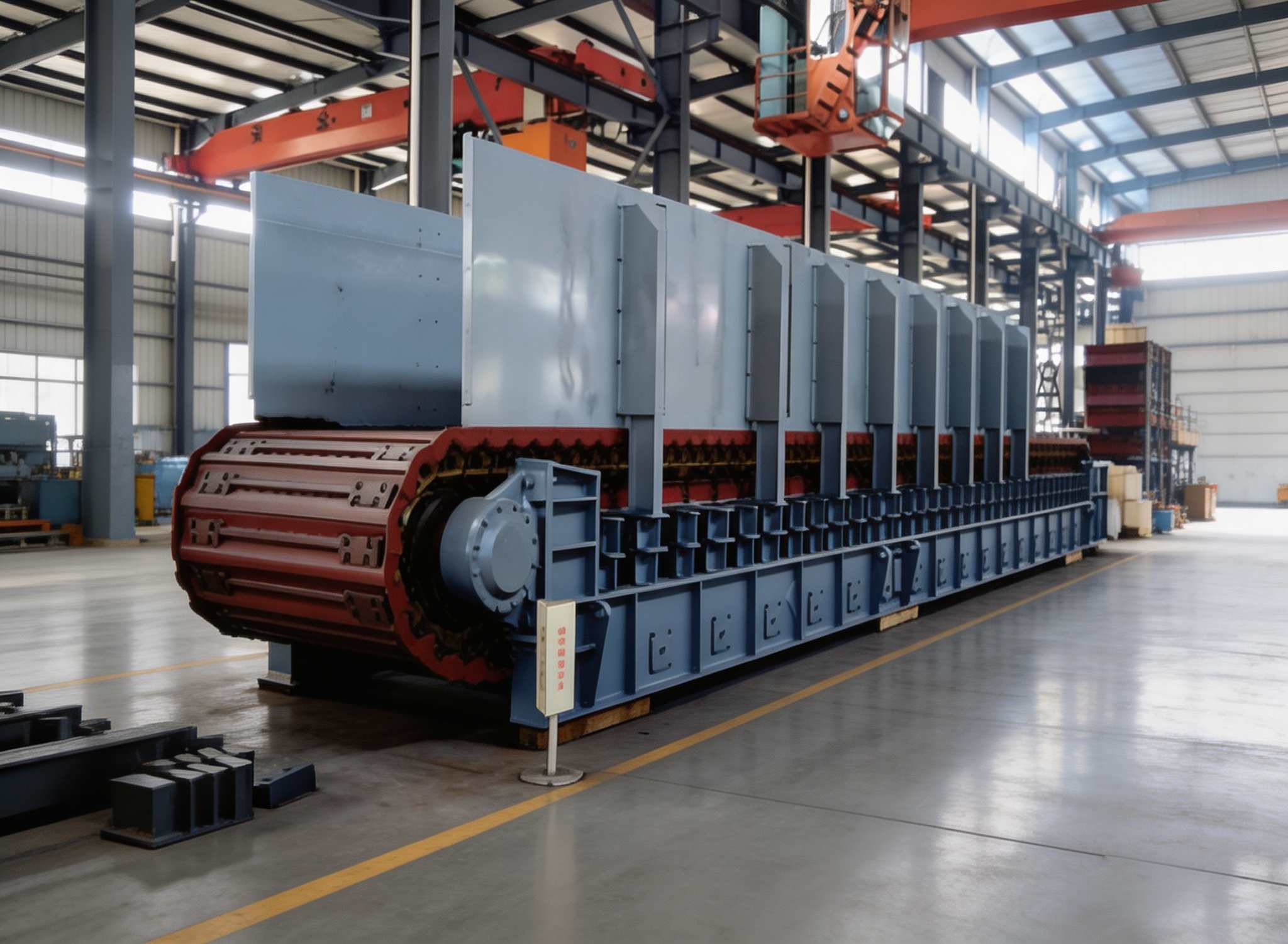
Load-carrying pans are made of 10-16mm thick manganese steel plate, capable of directly withstanding the impact of large materials falling from a 2-5m height from mine cars or bins, making it the only feeding equipment that can withstand direct mine car dumping. The pans have reinforcing ribs on the back for improved bending stiffness, preventing plastic deformation even under repeated impact from large ore.
The traction chain and load-carrying pan are independent. The traction chain only transmits power and bears tension, while the pans independently bear material weight and impact. Damaged pans can be individually replaced without affecting the whole machine. The traction chain does not directly contact materials, resulting in low dynamic load and light wear, extending overall machine life by 2-3 times. This is the core advantage of the BW series over traditional apron feeders.
BW2400 has a max feed size of 1500mm, capable of directly receiving blasted run-of-mine ore (no secondary crushing needed) and feeding directly into primary jaw or gyratory crushers. With pan width of 1000-2400mm and 8 models, it fully covers all capacity requirements from small aggregate lines to large open-pit mines.
The low-profile tail structure plus large-angle transition section design eliminates the chronic problem of material buildup and chain jamming at the tail of traditional apron feeders. Sticky-wet materials (such as high-moisture laterite nickel ore, clayey limestone) are not prone to accumulation and adhesion at the tail. Excellent performance in rainy humid regions and non-metallic mines, with equipment availability far exceeding vibrating feeders.
60-1900 t/h (BW1000→BW2400), covering the full capacity range from small-medium quarries to super-large open-pit mines. VFD allows online stepless adjustment of feeding rate (20-100%), precisely matching downstream crusher capacity. Interlocked control with crusher load prevents overload and idling, improving overall line efficiency.
Can operate stably long-term in open-air, high-temperature, dusty, and rainy environments. All-steel structure eliminates the need for rubber belts (no aging problem). The overlapping design of pans allows fine materials entering gaps to be discharged. Daily maintenance only requires lubricating chain pins and checking pan bolt torque, with maintenance workload and operating costs far below belt conveyors.
In large metal mines, mine cars dump blasted run-of-mine ore (up to 1500mm) directly into the apron feeder trough. The feeder delivers ore at a stable rate to the gyratory crusher. BW2200-BW2400 are standard supporting feeding equipment for gyratory crushers, capable of withstanding 60-100 ton class direct dumping impact from mine cars.
In aggregate production lines and small-medium beneficiation plants, BW1000-BW1800 apron feeders are installed under bins to uniformly feed 500-800mm ore into jaw crushers. VFD automatically adjusts feed rate based on jaw crusher working current, preventing blockage and overload shutdown.
In open-pit crushing stations, mining dump trucks directly dump large ore into the apron feeder receiving trough. The heavy-duty pans and buffer structure can withstand repeated impact from truck dumping, making it the only feeding equipment suitable for this working condition. Combined with a hydraulic rock breaker, it can handle oversized ore online.
In cement plant limestone crushing workshops, dump trucks discharge limestone (≤800mm) into the receiving hopper. The apron feeder uniformly feeds material from under the hopper into hammer or impact crushers. The well-sealed design of the BW series can work with dust collection systems, meeting strict cement plant emission standards.
In steel plant sintering and pelletizing plants, multiple apron feeders form batching systems that proportionally extract iron ore, limestone, coke fines, and return fines from batching bins and feed them into mixing lines. VFD enables precise ratio control with error ≤2%.
In large aggregate production lines, the apron feeder serves as primary feeding equipment, extracting material from under the ROM bin and uniformly feeding it into the jaw crusher. Compared to vibrating feeders, apron feeders have better adaptability to high-clay-content and large-size materials, and are less prone to blockage and arching in the trough.
Need an Apron Feeder? Contact us for a selection solution and quotation